What is the principle of smart lock technology? For professionals, it is not difficult to understand the working principle of smart locks, each technology has a large amount of data query, but for ordinary users who want to understand smart locks, understanding the general principles is more conducive to understanding the industry, Learn about the use and maintenance of smart locks. Here introduces the working principle and hardware composition of the smart lock.
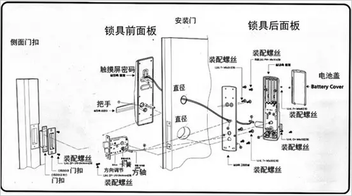
Overview of the basic hardware composition and structure of smart locks
The intelligent password lock system consists of an intelligent monitor and an electronic lock. The two are placed in different places, and the intelligent monitor supplies the power required by the electronic lock and receives the alarm information and status information sent by it. Here, the line multiplexing technology is adopted to make the power supply and information transmission share a two-core cable, which improves the reliability and security of the system.
How Smart Locks Work
1. The basic principle of smart monitor
The intelligent monitor is composed of MCU, clock, keyboard, LCD display, memory, demodulator, line multiplexing and monitoring, A / D conversion, buzzer and other units. It mainly completes functions such as communication with electronic locks, intelligent analysis, and security monitoring of communication lines.
The intelligent monitor is always in the receiving state, receiving alarm information and status information from the electronic lock in a fixed format. For alarm information, an audible and optical alarm is immediately issued through the LCD display and buzzer; for status information, it is stored in memory and compared with the historical state of the electronic lock before this moment, to obtain the change trend and predict the future The status changes, and the corresponding information is provided to the duty staff through the LCD display for decision making. While the intelligent monitor establishes communication with the electronic lock, it monitors the change of the power supply current flowing through the communication line in real time through the A / D converter, effectively preventing the damage caused by human factors, and ensuring the smooth communication line.

2.Basic principle of electronic lock
The electronic lock is also based on the 51 series single-chip microcomputer (AT89051) with corresponding hardware circuits to complete the password setting, storage, identification and display, drive the electromagnetic actuator and detect its drive current value, and receive the alarm signal sent by the sensor , Send data and other functions.
The single-chip computer receives the code entered and compares it with the password stored in the EEPROM. If the password is correct, the electromagnetic actuator is unlocked. If the password is incorrect, the operator is allowed to re-enter the password, which can be entered three times. If it is correct, the single-chip microcomputer alarms the intelligent monitor through the communication line. The single chip microcomputer sends each unlocking operation and the driving current value of the electromagnetic actuator at this time as status information to the intelligent monitor, and at the same time sends the alarm information received from the sensor interface to the intelligent monitor as a basis for intelligent analysis.
Detailed analysis of the principle of smart lock technology
In order to improve the security and reliability of smart password locks, in addition to taking measures in device selection (such as using low power consumption and wide temperature range devices), this article also uses some key technologies in the design.
2.1 Line Multiplexing Technology
Smart monitors and electronic locks are placed off-site. If the communication line and the power supply line are separated, the number of cable cores will be increased, and the safety hazard will increase. This article uses line multiplexing technology, using only a two-core cable to achieve power supply and information transmission.
At the transmitting end, the electronic lock device boosts the modulated data signal through the pulse transformer T and sends it out; at the receiving end, the pulse transformer T steps down the received data signal and sends it to the demodulator to reduce the carrier signal during the transmission process. In the loss. In order to reduce mutual interference between communication and power supply, the choice of choke coil L and coupling capacitor C should be comprehensively considered.
Set the carrier frequency fo = 400kHz. In order to ensure that most of the signal energy is transmitted to the receiving end, take L = 33.7μH? C1 = 0.047μF.
2.2 Current monitoring technology
In order to prevent the artificial damage of the communication line and the electromagnetic actuator from burning the coil due to excessive current flowing through the electromagnetic coil for some reason, this paper uses current monitoring technology in the design of the smart combination lock.
2.3 Data communication and preprocessing technology
The intelligent monitor receives the status information (including the opening and closing of the lock, the wrong password for the first time, the wrong password for the second time, the wrong password for the third time, etc.), the current value flowing through the coil of the electromagnetic actuator, and Reading the power supply current value of the communication line at this moment, the three together combine to form a data block, in which the operating state occupies 1 byte, the power supply current occupies 2 bytes, and the coil current occupies 2 bytes. The intelligent monitor is always in the receiving state during communication with the electronic lock. In order to improve the reliability of communication, this article adopts the repeated sending method in the communication protocol. The electronic lock repeatedly sends each group of data 5 times. After the intelligent monitor receives this group of data, it uses the large number decoding law to correct the error, ensuring that The accuracy of the data received.
In addition, in order to save memory, it is necessary to use pre-processing technology for the received data, that is, after each data is received, it is first compared with the set threshold. If it is greater than the threshold, an over-limit alarm is issued; if it is less than The threshold value is compared with the similar data received on the same day, and the larger one is retained. In this way, the data stored every day is the largest value of the same kind of data.
STF224 Series Alternator Suppliers
1.Balanced rotor with single or two sealed ball bearings
2.Any permanent magnetic generators, providing invariable excitation on all occasions.
3.Easy to be connected with power network or other generators. Standard 2/3 pitch windings
check excessive midline current.
4.Convenient installation and maintenance with easy access to terminals, rotating diodes and
coupling bolts
5.Meet leading standards
6.Wide range of Flange adaptor and single bearing coupling disc

