ZX Series Of Self-Priming Pump Centrifugal Pump,Self-priming Pump,Stainless Steel Water Pump,Electric Water Pumps Sewage pump,Water pump Co., Ltd. , http://www.nbagriculturalpump.com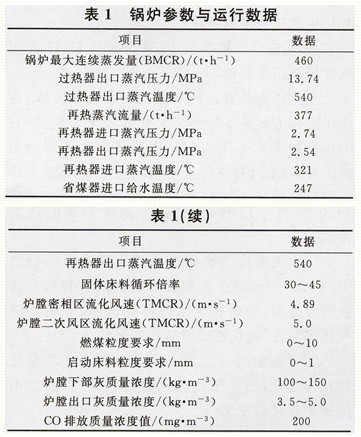
After the CFB boiler's fuel is broken and sieved, it enters the coal-receiving tube through the coal feeder and is sent into the lower half of the dense phase area of ​​the furnace by the sown coal air. It is surrounded by high-temperature materials and is heated, precipitates volatile matter, and burns. The coke is Combustion is accompanied by high-speed air flow in the combustion chamber in boiling suspension. At the same time, the high-temperature flue gas carries part of the high-temperature materials and unburnt coal particles flying out of the combustion chamber, and the unburned fuel separated by the cyclone separator is returned to the bottom of the furnace by the returning device, and is again entered into the furnace to circulate and burn.
2.2 Air volume composition The operational characteristics of the CFB boiler determine the special composition of its combustion air, consisting of primary air, secondary air and high pressure fluidized air.
The primary air is sent to the hearth through the air distribution plate at the bottom of the hearth. The role of the primary air is firstly fluidized bed material, followed by the amount of oxygen at the initial stage of combustion, and the other purpose is to bring the heat generated in the dense phase area to the rare phase area. A certain bed temperature ensures the heat transfer from the furnace.
The secondary air is sent into the hearth by the secondary fan through the air duct at a height of about 0.5 to 6m above the air distribution plate. The higher the wind speed, the stronger the penetration force, and the unburned carbon particles in the dense phase zone. Carbon monoxide gas, etc. are mixed to provide the oxygen required for combustion.
The primary and secondary air volume of the CFB boiler changes with the change of the boiler load, but the high-pressure fluidized air flow remains basically stable and does not change with the boiler load.
The CFB boiler's air volume control is the key and the requirement is very high. Its proportioning adjustment can adjust the primary air volume corresponding to the change of the load (ie, the coal supply quantity) under the premise of guaranteeing the fluidization, so as to meet the combustion share and the heat distribution in the furnace. The secondary air volume meets the oxygen required for combustion and penetrates to enhance combustion. Before the operation, cold test is needed. After the test, the critical fluidization air volume curve of different material layers is obtained. Then the critical fluidization air volume curve of different material layers in the standard state is calculated through the correction of the temperature. The benchmark for air volume. The amount of secondary air can be adjusted with reference to the amount of oxygen in the flue gas at the furnace outlet. In this way, in the hot state, the coal is fully burned in the hearth by adjusting and matching the primary and secondary air volume. Through optimization and adjustment, the first and second air volume can reach the best match, so that the bed temperature, bed pressure, steam temperature and other parameters can reach the best operating conditions.
2.3 Operating characteristics The secondary air volume is an effective means to ensure the normal fluidization of the bed material and to regulate the furnace temperature. The consequences of a small amount of air flow in the boiler operation are: First, the fluidization of the bed material is not good; second, the amount of oxygen required for combustion in the dense phase area is not reached; the amount of heat released by the fuel is small, which will cause the bed temperature to rise; The small amount of heat carried by the dense phase area will also cause the bed temperature to rise and cause overheating or coking. When the air volume is large at one time, the heat carried out from the dense phase area is greater than the heat generated by the combustion of the fuel, the bed temperature will drop, the flow rate of the flue gas will be larger, and the wear of the heating surface will increase. Increasing the air volume before adding fuel is sometimes not conducive to controlling the bed temperature, but the air must be reduced after the fuel is reduced. The secondary air volume is generally 40% to 50% of the total air volume, but this is not fixed. The operation should be adjusted according to the different types of coal and the degree of dryness and wetness of the coal and the size of the particle size. This requires the actual combustion of the boiler. The situation is judged and adjusted to make the boiler safe and economical.
Third, the CFB boiler control program and control characteristics CFB boiler fuel fluid combustion state determines its combustion system is a large lag, a strong combination of nonlinear systems, the interaction between various variables, plus a fly ash cycle, The combustion process is more complicated than the pulverized coal boilers: some of the adjusted parameters are simultaneously affected by several adjustments. For example, the bed temperature is controlled by parameters such as coal supply, primary air flow, return flow, and slag discharge amount; some The adjustment amount also affects a plurality of adjusted parameters at the same time, for example, the coal supply amount not only affects the main steam pressure, but also affects parameters such as the bed temperature, the furnace temperature, the air excess coefficient, and the CO and SO2 volume fraction (content).
For CFB boilers with such large delays and strong couplings as non-linear systems, in order to coordinate the control of the boiler steam turbine, and ensure the stable operation of the unit, the control system design adopts the turbine control pressure, the boiler combustion control stable load, and the primary and secondary winds. Matching stable bed temperature basic control program.
3.1 Main steam pressure control system Main steam pressure control system is realized by DCS through DEH control turbine control door.
The main steam pressure has two control modes: constant pressure and sliding pressure: under the constant pressure control mode, the operator sets the pressure constant value; in the sliding pressure control mode, the pressure setting value is given according to the unit load instruction. Taking into account the characteristics of CFB boiler's large delay, the setting method of the sliding pressure setting in the debugging is modified to be that the pressure setting comes from the actual power of the unit when the load is changed, and the steady state pressure setting comes from the unit load command.
The relationship between pressure setting and load is shown in Table 3. 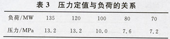
Due to the slower response of the CFB boiler to the load, in order to increase the response speed of the unit to the load, the pressure setting will be dynamically changed when the variable load is added during system commissioning, and the purpose of using the boiler energy storage when the turbine door opening is changed to achieve variable load is changed. Improve the unit's ability to respond to loads.
The relationship between the change of the pressure setting value and the load deviation during variable load is shown in Table 4. 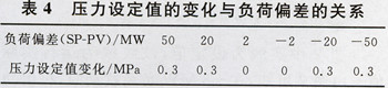
3.2 Primary air control system The primary air must first ensure the fluidization of the bed material. The primary air control is to ensure the fluidization and meet the reasonable combustion heat distribution requirements. Adjust the secondary air to ensure a reasonable amount of wind in the furnace, so the primary air control The command is a function of unit load.
The primary wind has two local and remote control modes: local control is the operation personnel changes the primary air supply value to control the primary air volume of the boiler; the remote control is based on the total air flow instruction issued by the power controller, and the primary air command is generated by the total air volume command. And secondary air instructions. When the unit is put into coordinated control mode, the primary air should be placed in a remote way.
In the remote control mode, the relationship between the primary wind command and the total air volume is shown in Table 5. 
The relationship between the boiler command and the total wind command is shown in Table 6. 
The secondary air has two local and remote control methods: the local control is controlled by the operator to change the secondary air supply value to control the secondary air flow of the boiler; the remote control is based on the total air flow command issued by the power controller, and is generated by the total air flow command. Secondary air directive. When the unit is put into the coordinated control mode, the secondary air should be placed in a remote way. In the remote control mode, the relationship between the secondary air command and the total air volume is shown in Table 7. 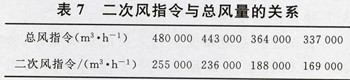
3.4 Oxygen content control system The oxygen content (volume fraction) control system mainly corrects the secondary air according to the unit load to ensure the excess air coefficient of the boiler combustion.
Oxygen has both on-site and remote control methods: on-site control is to change the oxygen setpoint by the operator to control the boiler's oxygen level; remote control is to issue the oxygen demand according to the unit command. When the unit is put into coordinated control, the amount of oxygen should be placed in a remote way.
The relationship between oxygen content and unit load is shown in Table 8. 
3.5 The combustion control system timely controls the secondary air baffle according to the unit load. Under the premise of stable secondary air volume, it can ensure the penetration of the secondary air.
There are 18 secondary air baffles on the front and rear walls of the boiler: 10 secondary air baffles on the front wall and 8 secondary air baffles on the back wall; the secondary air baffles on the front and rear walls are divided into secondary windshields. Plate and lower secondary baffle.
The control system allocates four operators to the front and rear wall secondary air baffles for the operation of the upper and lower secondary air baffles on the front and rear walls.
When the secondary air baffle is in automatic, the secondary air baffle receives the unit load command. See Table 9 for the relationship between unit load and upper and lower secondary air baffles. 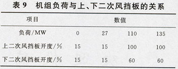
3.6 Fuel Control System The fuel control system accepts the coordination of the main control combustion instructions and controls the fuel quantity to ensure the unit load.
The fuel has two local and remote control modes: Local control is the change of the fuel supply value by the operating personnel to control the boiler fuel volume; the remote control is based on the power controller to issue fuel instructions. When the unit is put into coordinated control, the fuel should be placed in a remote way.
3.7 Coordinated Control System Coordinates the master control system to accept the load instructions of the operating personnel, coordinates the turbine control guarantee pressure, and controls the combustion to ensure the unit load.
When coordination of the main controller is automatic, steam turbine pressure regulation is realized, and the boiler fuel, primary air, and secondary air commands are sent through the power controller to achieve coordinated control of the unit.
IV. Commissioning and tuning of the control system After careful debugging and tuning at the site, the CFB boiler and unit control system were stably put into use. The control performance and quality have met the requirements for stable operation of the unit.
Coordinated control of the operating mode, load of the unit under steady load conditions, main steam pressure, oxygen content, primary and secondary air, and fuel change curves are shown in Figure 1. 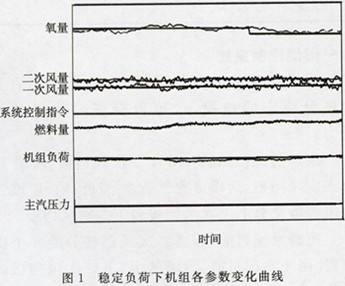
The solid line in Fig. 1 is the setting value, and the wavy line is the actual value of the operation. Figure 1 shows that, under steady load conditions, the unit load, main steam pressure, oxygen content, primary and secondary air volume, and fuel parameters all fluctuate within a small range, and the control is smooth.
In the coordinated control mode, ±5MW was applied to the unit. From Fig. 2, we can see that in the ±5MW load disturbance, the unit power, main steam pressure, fuel, oxygen amount, and primary and secondary air flow changes are stable, and the response time meets the requirement of variable load. 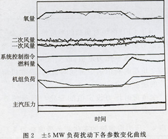
V. Conclusion Through the debugging of the coordinated control system, the furnace has achieved automatic control, and the following conclusions can be obtained:
(1) It is feasible to achieve automatic combustion on a CFB boiler, but it should have certain external conditions. It is important that the fuel is relatively single and stable, because the factors that affect the combustion instability are the changes in the fuel, so that the wind coal determined in debugging is determined. The relationship between the relationship and the relationship between primary and secondary air can not meet the actual operation requirements.
(2) The design data provided by the manufacturer needs to be inspected during actual operation. The design calculation value of the manufacturer extracted from the CFB project in India is far from the actual operation value and cannot be matched with the actual operation parameters. The extraction of various types of parameters was directly extracted from the field-accurately adjusted combustion matching parameters, and was verified by on-site configuration test and debugging.
Debugging and Application of 460t/h Circulating Fluidized Bed Boiler Combustion Automatic Control System
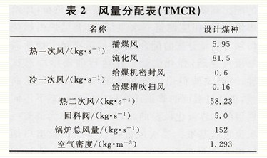
I. Boiler parameters and operating data The boiler parameters and main operating data are shown in Table 1, and the air volume distribution (TMCR) is shown in Table 2. Second, the CFB boiler combustion process and operating characteristics 2.1 The combustion process CFB boiler gas-solid two-phase flow and combustion process characteristics and pulverized coal furnace there is a big difference, mainly in the circulation and the amount of fluidization and other parameters of the furnace Effect of heat transfer. In addition, the unique combustion method of the CFB boiler also has the advantages of wide fuel adaptability, low pollutant emission, and comprehensive utilization of ash residues. 3.3 Secondary air control system During the operation of the unit, the secondary air control mainly ensures the excess air coefficient of the boiler to ensure the stability of the boiler combustion, and at the same time, the primary air is matched to ensure the boiler bed temperature. Therefore, the secondary air control command is a function of the unit load.