Welding Wire, Welding Wire,Welding Rod,Welding Equipment Welding Wire,Welding Consumables Co., Ltd. , http://www.nbweldingwire.com
As shown in Fig. 1, the transmission system is started from the origin and travels to 1000mm at medium speed, starts high-speed driving, runs to 3000mm at high speed, starts low-speed crawling, and crawls at low speed to the end point (3200mm). Pause for 2s. Reverse high-speed driving, high-speed driving to 200mm from the origin began to crawl at low speed. Stop at the origin and stop again after 2s. The purpose of the low-speed crawl at the origin and the end point is to avoid the fixed-point error caused by the inertia of the system, so that the original point and the end point can be accurately positioned to stop. 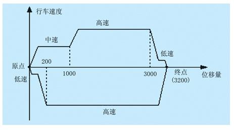
2. The speed of the system is adjusted by using frequency converters, positioning control using photoelectric encoders and PLC high-speed counters to accurately locate. As shown in figure (2) inverter and PLC wiring diagram. 
The forward and reverse rotation of the inverter is controlled by two contacts of the relays KA1 and KA2 (corresponding to the PLC output points Q0.0 and Q0.1), and the speed switching is completed by the relay KA3 and KA4 contacts (corresponding to the PLC output point Q0.2, Q0.3). The inverter fault alarm output contact (30A, 30C contact) is used to immediately stop the high-speed counter operation and is indicated by the indicator HR (corresponding to the PLC output point Q0.6).
Inverter has multi-speed setting function, when both KA3 and KA4 contacts are disconnected, high-speed driving (first speed); KA3 is closed, KA4 is disconnected, medium speed driving (second speed); KA3 is disconnected When the KA4 is closed, the vehicle runs at a low speed (third speed); when both KA3 and KA4 are closed, the vehicle is manually adjusted (fourth speed).
Knob SF1 (I0.1) is used for manual/automatic switching and indicates automatic status with indicator HG1 (Q0.4). Manually, the position of the drive system can be manually adjusted via the buttons SA1 (Forward rotation of the motor) and SA2 (Reverse rotation of the motor).
The button SA (I0.2) is used for start/stop control of the drive system in the automatic state. The start/stop control is realized by the “one-key switch†method, and the start status is indicated by the indicator HG2 (Q0.5).
When the travel switch SQ (I0.5) is used for automatic start-up, it is determined that the drive system is at the origin position. When it is automatically stopped, the drive system must return to the origin. Travel switches SQ1 (I0.6), SQ2 (I0.7) are used to limit the two ends of the transmission system to ensure that the drive system cannot be disconnected from the equipment.
3, PLC program flow chart automatic operation program: SBR_1, as shown in Figure 3. 
Interrupt handler: INT_0, as shown in Figure 4. 
4, the key technologies (1) high-speed counter interrupts and multiple changes to preset values ​​to achieve multi-point positioning The key to achieve multi-point positioning control includes two points, the first point is to set the high-speed counter interrupt event 12 (counter current value = counter pre The other point is to change the high-speed counter preset value in the interrupt handler.
The positioning control determines the positioning point by determining the distance between the positioning point and the origin.
To measure the distance traveled by the equipment, the unit distance (mm) needs to be converted into a pulse quantity, and the change of the pulse quantity is recorded by a photoelectric encoder and a PLC high-speed counter.
The mechanical axis of the photoelectric encoder and the motor are coaxial. Transmission ratio = 10, drive rod diameter for driving equipment = 100mm, photoelectric encoder pulse per revolution = 600. The number of pulses per millimeter of distance can be calculated as:
Number of pulses per millimeter distance = 600 ÷ (10 x 100 x 3.14) ≈ 0.19108 pulses/mm
Compared with fixed-point and preset values, the high-speed counter interrupt mode must be adopted instead of the general comparison instruction. Because the general comparison instructions cannot catch high-speed changing events.
Therefore, the high-speed counter interrupt event number 12 (counter current value = counter preset value) must be connected to the interrupt handler INT_0 through the ATCH and ENI instructions. In the interrupt handler INT_0, when the preset value is reached, the next preset value is reloaded, and the relay output requested by the process is executed to process the operating speed of the inverter.
In the automatic subroutine SBR_1, the high-speed counter HC0 is set as a single-phase count input and the external control function is cancelled. By changing the counting direction at the origin and the end point, the interrupt handler INT_0 can be used to judge the running direction of the inverter.
(2) The equal compare instruction cannot be used in the interrupt handler INT_0 because it is determined to process a plurality of preset values ​​in one interrupt handler INT_0. It is necessary to compare the instruction and the counting direction to judge at which stage the current high-speed counter counts the current value, and determine which section of the instruction to execute according to the judgment. However, the judgement cannot use the equal to comparison instruction, and should use greater or less than the instruction judgment.
Although the interrupt event (counter current value = counter preset value) occurs, the PLC immediately interrupts the current main program, subroutines, and executes the instructions in the interrupt handler INT_0. However, in the interrupt handler INT_0, the PLC is still executed on a row by row scan mechanism. However, it is not possible to synchronize the count value of high-speed change with the execution of the interrupt handler. If equal compare instructions are used, the PLC may miss the equal value when executing the interrupt handler, making it impossible for the PLC to determine the stage to which the device is running in the interrupt handler.
(3) In automatic operation, writing of the initial value register of the high-speed counter must be prohibited because the multipoint positioning requires multiple times to load the preset value, and the HSC instruction must be executed to write the preset value.
When the HSC write command is executed, the preset value is not simply written. If there is no limit in the control byte, the value in the initial value register SMD38 is also written. SMD38 = 0, this will make the high-speed counter count the current value is set to 0. Therefore, in the automatic operation, the seventh bit SM37.6 of the control byte SMB37 must be set to 0, and when the preset value is loaded, writing of the initial value is prohibited.
However, when the high-speed counter is initially set and the operation is returned to the origin, the initial value must be written again so that the initial value is set to 0 to avoid errors caused by mechanical reasons. Therefore, the control byte must be modified multiple times. The following principles are followed: After the initial value is allowed to be written and the HSC instruction is executed, the control byte must be modified immediately, the initial value must not be written, and the HSC instruction must be executed again. No other instruction can exist in the middle. Because PLC executes instructions one by one, row by row, and there are no other instructions, it will not have unnecessary influence.
(4) The multi-point positioning output coil uses the high-speed counter to perform multi-point positioning as soon as possible, mainly for accurate positioning. The positioning accuracy is determined not only by the measurement of the high-speed counter, but also by the execution speed of the actuator.
If ordinary output instructions are used, during the program execution phase of a scan cycle, only the output of the image memory is changed, and the output point of the PLC will not be immediately refreshed. Only after the program execution is complete, the output image memory of the PLC can refresh the output point. Execute the output.
In order to increase positioning accuracy, immediate output instructions are used as much as possible. The immediate output of the instruction is not limited by the PLC scan cycle. When the output image memory is changed, the PLC output point is immediately refreshed.
(5) Automatic/manual programs are implemented using For-Next loop instructions and subroutine instructions because of the auto/manual function. Automatic/manual programs use For-Next instructions and subroutine instructions. Automatic programs and manual programs are actually the body of two loop instructions. The loop instruction only performs a cyclic scan refresh.
The manual subroutine SBR_0 and the automatic subroutine SBR_1 are used for the segmentation of the entire program to facilitate the understanding of the program and increase the readability of the program.
The purpose of the For-Next loop instruction is to enable the output coil to be reused, simplifying the program. Because the execution of the two loop instructions is controlled by the knob SF (I0.1), it is impossible to execute them at the same time, and the programs in the loop body cannot scan and refresh at the same time. In this way, the output coil can be reused, and there is no need to use an intermediate variable conversion, which greatly simplifies the programming of the program.
The use of subroutines or jump instructions alone can also achieve repeated use of output coils, but it is cumbersome to switch between subprograms and the layout of jump instructions.
Using the For-Next instruction and the subroutine combination method, it is possible to avoid the cumbersome switching process. In the respective subroutine, the program is compiled, and it is not necessary to consider the other party's program completely as an independent entity. The only disadvantage of this method is that the respective initialization programming is duplicated, but it does not affect the device operation.
5. Concluding remarks The problem of high-precision multi-point positioning of mechanical devices is widespread in the control system of the processing industry and manufacturing industry. The system introduced in this paper is compact, safe, and reliable. It is very practical.
Using PLC and frequency converter to realize multi-point positioning and back-and-forth motion of mechanical transmission
1. INTRODUCTION In many reciprocating transmission control systems, multipoint positioning is involved. Different mechanical actions are initiated at different positioning points. Figure 1 shows the schematic of the mechanical transmission of the planer.
Figure 1 Transmission diagram of a planer
Figure 2 (a) PLC wiring diagram
Figure 2 (b) inverter wiring diagram
Figure 3 automatically run the program